Introduction
This reconstruction is based on analysis of the original Cheiroballistra text as well as available English editions of the cheiroballistra (Marsden 1971: 206-233; Wilkins 1995: 10-33). Ideas from a number of earlier scholars, especially Iriarte (2000; 2003), are utilized where they seem to make sense. Additionally I've used the manuscript diagrams available in Schneider's (1906) and Wescher's (1867) editions. Analysis of the archaeological finds is mostly based on the numerous publications of Baatz.
In this article and reconstruction I've made a few underlying assumptions and followed a few key principles:
- Pseudo-Heron's (P.H.) cheiroballistra text is assumed to be more or less complete. No parts are assumed missing, unless it's certain that the reconstruction can't work without them. If a certain component is not described in much detail, it is assumed to have been well-known to the ancient artificer reading the text or so simple, that it required little explanation.
- Archaeological finds are given preference to text in case of ambiguities. They are, however, only used to make design decisions where the text fails. Dimensions from archaeological finds are not used, even if they seem similar to those in the text.
- The goal has been to make the reconstruction fit the text, not vice versa. This principle is followed as far as reasonably possible. For a good example of this principle, see the discussion below about the tenons of the rungs in the little ladder.
- I do not try to hide problems in the source material or in my own theories. Therefore I've tried to make it clear what we really know and what is subjective. My goal is to make (constructive) critique as easy as possible, not to protect myself from critique by not mentioning the issues I've encountered.
The cheiroballistra text is a description of interrelated ballista components. Although the assembly instructions are very incomplete, the fact that parts must fit together helps a lot in making the reconstruction correct. If an incorrect change is made to dimensions of some component, it is likely that problems arise elsewhere. There are two possibilities to coping with this. The first option is what some scholars unfortunately seem to do: hang on to their assumptions and force the sources to fit them. For discussion of this issue see Iriarte's JRMES article (2000: 56-57). The second option is to question one's underlying assumptions and think "outside the box", trying to find the most logical explanation to the problem. I have tried to follow the second option according to my best ability. I've also tried to follow the principle of Occam's razor according to the best of my ability.
One big problem with the work of many previous scholars is that they have ignored the limitations of the metalworking techniques and tools used by the Greeks and the Romans. To arrive at a realistic reconstruction, these need to be taken into account. Again, there's a good example of this in the little ladder section.
Sources
The most useful cheiroballistra editions can be summarized as follows:
- Marsden's (1971: 212-217) edition and English translation. Does not contain any manuscript diagrams.
- Wilkins (1995: 5-59) edition and English translation. Contains most of the manuscript diagrams.
- Wescher's (1867: 123-134) edition and Latin translation. Contains many manuscript diagrams.
- Schneider's (1906: 142-168) edition and German translation. Contains photographs of many manuscript diagrams.
- My own English translation. While certainly not the best translation/edition there is, it's the only modern translation that's freely available on the Internet. Moreover, it's released under a Creative Commons License allowing it to be used and improved with very few restrictions. For availability of the other editions take a look at the bibliography page.
In addition, several articles discussing the cheiroballistra have been written. Most noteworthy is the Iriarte's JRMES article (2000: 47-75). His follow-up article published in Gladius (2003: 111-140) also contains useful information regarding inswinging ballistas, including the cheiroballistra. All articles of Baatz are very useful, because they contain descriptions and pictures of archaeological finds belonging to late-Roman cheiroballistra-style ballistas. As these archaeological finds clear up lots of the confusion in the cheiroballistra text, Baatz' contributions have been extremely valuable to the research.
Wilkins' JRMES articles (1995; 2000) and his small book, "Roman Artillery" (2003) require special mention. They should be used with caution for two reasons: Wilkins' decided to reconstruct his cheiroballistra as a winched weapon and as an outswinger. There are very little evidence supporting either of those interpretations, so the authenticity of Wilkins actual reconstruction is questionable. That does not in any way diminish the valuable contribution he made by making another English edition of the cheiroballistra and by interpreting some of the cheiroballistra's components in a way that stands the test of time. Also, Wilkins' versions of the manuscript diagrams are of excellent clarity.
The availability of these sources varies greatly. A few of them can be ordered or bought from the Internet. Some are freely available. Some are nearly impossible to obtain without some creativity and help from fellow enthusiasts or friends in world's most highly rated universities. This is unfortunate, as it greatly limits the people who can - in practice - study this fascinating subject. Take a look at the bibliography page for more information about the availability of the various sources.
Main controversies
Outswinger or inswinger
Archaeological finds strongly suggest that the cheiroballistra was an inswinger so I've reconstructed it as such. This issue has already been discussed in detail here.
Winched or not winched?
The cheiroballistra was almost certainly a personal weapon and as such did not have a winch. The reasons for this are discussed in detail on this page.
Conventions
All measurements are in Greek dactyls (1,93cm). One Greek foot is 16 dactyls. The way dimensions are marked in the CAD drawings requires explanation:
- Dimensions which are clearly stated in the cheiroballistra text are marked in green. Even these dimensions may be suspect as it is not always clear what P.H. means by width, thickness, length and breadth. That said, the vast majority of these dimensions can't really be questioned.
- Dimensions which roughly know are marked in orange. These are the ones given in the text as "about x dactyls". This applies mostly to the slider width.
- Dimensions which are derivable from other dimensions are marked in magenta. These dimensions are not stated in the text, but can be calculated from dimensions of other parts. This applies especially to thickness of the field frame bars, which are referred to throughout the text.
- Dimensions which are entirely subjective and not given in text are marked in red. These dimensions are the ones which have allowed scholars to reconstruct the cheiroballistra as a winched weapon without amending the text too heavily.
In the few cases where the clearly stated or roughly known dimensions have been amended, the following notation has been used:
- X d (Y d)
- X d (Y d)
Where X is the amended measurement and Y the original measurement stated by P.H.
Cheiroballistra parts
Case
The case is the lower part of the cheiroballistra stock with a female dovetail groove running down it's length. The upper part of the stock, slider, has the male dovetail which allows it to slide on top of the case. Although the description of the case (e.g. Marsden 1971: 213) is relatively clear compared to most other sections in Heron's cheiroballistra, it can still be interpreted in a number of ways.
The part describing the location of the projecting block (ΚΘ) is corrupt in all manuscripts and does not make sense as is. A simple solution to this corruption was suggested first by Prou's (1877: 120-121) and later Iriarte's (2000: 48). Both simply substituted ΑΘ with ΛΘ and the text makes perfect sense. While this theory sounds most plausible to me, other explanations have been suggested by Marsden (1971: 218), Wilkins (1995: 11-12), Schneider (1906: 149) and Baatz (1974: 70).
The actual purpose of the projecting block has confused pretty much every researcher, as Iriarte (2000: 48) points out. I have interpreted it simply as a support for the little ladder holding the field frames. This is the simplest solution to keep the little ladder, the field frames and the little arch from moving backwards when the weapon is cocked. Of course, some additional ironwork is needed, but much less than without support from the projecting block.
As Wilkins (1995: 12) notes, removing wood along ΛΘ and ΑΚ as suggested by Heron (e.g. Marsden 1971: 213) seems silly. It seems clear that Heron is not thinking like a carpenter, who would have simply glued or nailed a piece of wood to bottom of the board ΑΒ and be done with it - as did I.
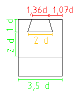
Full CAD drawing of the case below. Side, bottom and top views:

And the case from front:
Slider
The slider has a male dovetail corresponding to the female dovetail in the case. Although a relatively simple component, it's exact form is still not clear. There are two competing interpretations for the slider's cross-section:
- Most scholars (e.g. Marsden 1971: 218, Wilkins 1995: 11) have reconstructed the slider from two pieces forming a "T" shape. The lower part of this composite construction was the male dovetail to which the upper part was attached. The upper part simply rests on top of the case.
- Iriarte (2000: 52) suggests that the slider was made from one piece.
These differing interpretations stem from the fact that Heron did not state how wide the female dovetail should be; he only gives it's depth (1d) and length (46d). He also says that the slider should be "about" 2,5d wide and 1,25d high. The "T" proponents take 2,5d to mean the width of the upper (non-dovetail) part of the slider, whereas Iriarte (2000: 52) suggests that the male dovetail itself - being the only part of the slider - was about 2,5d wide.
I've personally followed Iriarte's interpretation as it is simpler and requires one to make fewer questionable assumptions. In addition, using a T-shaped slider places the slider too high, making the bowstring rub against the stock.
The "about" (see Iriarte 2000: 52) in slider width requires some discussion. If the slider was 2,5d wide, then only 0,5d (or ~1cm) of wood would be left on both sides of the slider. This is not much, but might be enough for durable operation. Nevertheless, I've made the slider slightly narrower (2d).
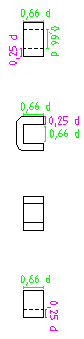
Below the slider viewed from side, bottom and top:

And from the front:

Crescent-shaped piece
The crescent-shaped piece (ΗΒ) has a rectangular hole in it's middle and it's attached to the end of the case. Apparently a rectangular tenon was pushed through this hole and into the stock to keep it firm. None of it's dimensions are given by P.H.
The crescent-shaped piece is used to push the slider backwards with stomach pressure. This interpretation is almost universally accepted by all scholars, with the notable exception of Alan Wilkins (1995; 2000, 2003). There is no need to find any other explanations unless one is predetermined to interpret the cheiroballistra as a winched weapon like Wilkins did.

Little ladder
Contents moved here.
Little arch
Content moved here.
Field frames
Bars
Field frames are spring-frames used to house the spring cord. Wescher's (1867) edition of the cheiroballistra does not unfortunately include pictures of these bars. Fortunately Schneider's edition (1906: 154) does. However, best illustrations are in Wilkins' edition (1995: 18). In addition, there are several archaeological finds of field-frames.
There are two field frames in each cheiroballistra, each consisting of one curved bar (ΔΒ and ΗΘ) and one straight bar (ΓΑ and ΕΖ). To the end of these bars two rings are attached at ΚΛ, ΜΝ, ΞΟ and ΠΡ. In codex M's diagram (see Wilkins 1995: 18) the Ζ is clearly in the wrong place - it should be next to Π. This does not affect the interpretation in any way, though.
Below is a diagram of the field-frame bars:

The characteristic curve in the middle of outer bars is formed by bending the thicker side of the bar. This method was used on some of the archaeologically attested field-frames, namely in Orsova and Lyon artefacts. This makes sense, as it does not make the curved bar too weak to withstand the pressure of the torsion springs. In Gornea field-frames the curved bar was bent along it's thinner side. However, the curved part of the bar was significantly widened, almost certainly to prevent the pressure of the spring cord from bending it. The curve in Gornea field-frames also seemed to be more modest than that in Orsova and Lyon field-frames. The Sala field-frame was cast from broze and it follows the Orsova / Lyon style.
Rings

Pi-brackets
Washers
Triggering mechanism
Content moved here.
Arms
Content moved here.
Assembling the components
Foreword
Correctly reconstructing the cheiroballistra involves assembling the components so that they work perfectly together. If some of the individual parts are misinterpreted, problems almost certainly arise when assembling the components. Marsden (1971) and Wilkins (1995) encountered a number of these problems because they had arbitrarily changed various dimensions of the cheiroballistra. I've used the relationship and interaction of the components as a guide: if the components don't seem to fit together, there more likely an issue with the interpretation rather than the sources themself.
Alignment of the field-frame bars
The distance between the field-frame bars is given as 3,5 d. We also know that the ring to which these bars are attached has external diameter 4 d and internal diameter of 2d. This is about all we know for certain. However, it is possible to align the field-frame bars so that these conditions are met and the necessary assumptions are so intuitive that P.H. could have omitted them intentionally or by mistake because of their obviousness. This rules out some of the more imaginative solutions suggested by some scholars.
As Iriarte (2000: 54-55) points out, all of the field-frame rings of manuscript diagrams (see Iriarte 2000: 54; Schneider 1907: 154-155; Wilkins 1995: 18) are pointed ellipses, not circles. Similarly, all of the archaeological field-frame rings are more or less pointed ellipses, Orsova field-frame ring being a good example of this. Therefore my cheiroballistra field-frame rings to some extent share this same feature. I also make a few other assumptions:
- Tenons of the little ladder beams are roughly identical in dimensions and form.
- The inner sides of the field-frame bars and outer extremities of the little ladder beams (not their tenons) are in contact.
- The center of the ring, washer and cord bundle is halfway between the ladder beams.
Given these assumptions, there is really only one way to align the field-frame bars correctly, if they're placed offset (left). If the bars are placed radially (right), another reconstruction is possible:

As can be seen above right radially placed field-frame bars require an asymmetrical ring; otherwise the curved bar will inevitably be farther from the ring's edge than the straight one. The beauty of the alignment above left - when coupled with the assumptions stated above - is that it requires no trickery or long chains of dependent arguments to support it. Also, as the distance between the little ladder beams is known, we can deduce that their thickness is ~0,17 dactyls. That is, if we assume the lower Pi-brackets of the field-frame bars are placed to their inside as discussed here. Only field tests will show if the thickness of the little ladder beams is enough.
The above placement of bars and rings will naturally make the cheiroballistra an inswinger. It is not possible to reconstruct any archaeological field-frame as an outswinger, and the close relation between those and the cheiroballistra has been acknowledged even by the outswinger proponents. This issue is discussed in more detail in here.
Attaching field-frames to arch and ladder
Attaching the little arch
All archaeological field-frames have four Pi-brackets attached to the field-frame bars. We can say without a doubt that the cheiroballistra was an inswinger. We can also say with reasonable certainty how their field-frame bars were aligned. With some help from archaeological finds - especially the Orsova one - it's relatively easy to see the most obvious way to attach field-frames to the little arch (viewed from the top):
The forked ends of the little arch pass through the Pi-brackets attached to the field-frame bars. The whole package was probably wedged together, one Pi-bracket at a time (Iriarte 2000: 62).
Attaching the little ladder tenons to Pi-brackets outside the bars
Unfortunately no remains of little ladders remain. In archaeological field-frames the lower pair of Pi-brackets is usually larger. One possible explanation for this is that their little ladders were made of wood. In cheiroballistra, however, the Pi-brackets are all the same size, so the little ladder was almost certainly made from metal similarly to the little arch. If we follow the example of the archaeological finds, the Pi-brackets have to be placed outside the field-frames. This means the tenons of the little ladder have to be spread out like this (top view):

There's probably no issue with this approach from structural perspective, but it means we have to make changes to the measurements P.H. gave us. This is the best point to discuss the critique Wilkins had against passing the little ladder tenons and the forked ends of the little arch through the Pi-brackets.
Wilkins (1995: 34) is correct in that the field-frame bars can't be made to fit neatly between the little ladder beams or the ends of the little arch. This is because dimensions given by P.H. are somewhat too small (see Marsden 1971: 215; Wilkins 1995: 24, 28). It is also true that both the arch and the ladder could have been simply made wider from the beginning, as Wilkins (1995: 34) says. That said, this problem becomes worse the thicker the field-frame bars are. And as discussed here the thickness of the bars is around 5mm, whereas Wilkins (1995: 20) made his 9mm thick. Therefore he had bigger problems than I. In my reconstruction with 4mm bars the gap in the little arch is only 0,34 d too small, which is easy to correct with a small bend. Also, as Iriarte (2000: 62) points out, it was impossible for P.H. to give an exact figure for the distance between forked ends of the arch, as it depended on the thickness of the field-frame bars which was left for the blacksmith (or engineer) to decide. In any case the little ladder is definitely too narrow: it should be 1d wider to fit over even my thin field-frames. However, as Iriarte (2000: 57-58) points out, the exact form of the little ladder beam tenons is unknown: this may be enough to explain the confusing dimensions P.H. gave us.
All this said, we can't ignore the most logical solution to the dimensions P.H. gave us: attaching the little ladder tenons to Pi-brackets inside the bars.
Attaching the little ladder tenons to Pi-brackets inside the bars
If we want to follow P.H.'s description closely, we have to make them slightly differently from the archaeological field-frames. This may be a lot to stomach for most scholars, but we should not forget that none of the existing field-frames belong to P.H.'s cheiroballistra. Therefore we can't take it for granted that it's field-frames were of the same kind. The easiest and most logical solution is to pass the tenons of the little ladder through a pair of Pi-brackets placed inside the field-frames. This option is shown in below diagrams, first from the top:

The green circle represents the diameter of the cord bundle. The same setup from the front:

If we place the lower Pi-brackets inside the field-frame all measurements fit perfectly, unless the spring diameter is arbitrarily increased (e.g. Wilkins 1995: 24). In fact, the width of the end of the little ladder beams is given as 1,25 d, and the width of the inside of the Pi-brackets as 2/3 d. This means that if we simply fold the ends of the beams along the long axis, they fit neatly inside the tenons (as shown above).
Even if the Pi-brackets are placed inside the field-frames, there's still a ~3mm gap between the the Pi-brackets and the torsion bundle before the arm is inserted. Experiments will show whether this is enough.
The only evidence against this interpretation comes from the manuscript diagrams, which definitely show both upper and lower Pi-brackets facing the same direction - away from the field-frames (see Schneider 1906: 154-115; Wilkins 1995: 18; Iriarte 2000: 54). The text itself does not state where the Pi-brackets are attached to (***reference***). This means that at this point we are forced to adjust the evidence to meet our expectations.
Whatever the truth is, Wilkins' use of little ladder's width as evidence against using the Pi-brackets for their most intuitive purpose does not sound very convincing (Wilkins 1995: 34).
Attaching little ladder to the case
The little ladder was attached to the case with T-clamps. As mentioned above, the projecting block under the case has been interpreted as a supporting block for the little ladder, which is very intuitive. Without this support block the T-clamps have to be exceedingly strong to prevent the little ladder from moving backwards. Wilkins (1995: 11) interpreted the block as an attachment point for the base whereas Marsden (1971: plates 7-8) ultimately ignored it. Both placed the little ladder close to the forward end of the case where it was not supported by the projecting block. This soon lead both into issues with draw length: even when the arms were drawn to the maximum, the slider was not entirely pulled back. The only way to fix this issue was to lengthen the arms, which allowed longer draw length (Marsden 1971: 226; Wilkins 1995: 33). As the length of the "cones" or wooden portions was known, only the metal hooks could be lengthened without contradicting the text. As explained above, lengthening the hooks beyond the cones is a bad idea. Also, as can be seen from the below diagram there's no reason to lengthen the arms to obtain the correct draw length with an inswinger. Interestingly same draw length can be obtained with an outswinger, too (Iriarte 2000: 65).
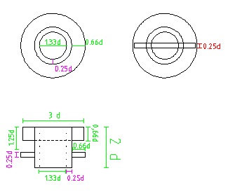
Below the little ladder, case and T-clamps from the side:

And from the front:

A few interesting things can be seen from these diagrams:
- There's no reason to change P.H.'s measurements (3d long, 1d wide) like Marsden (1971: 225) and Wilkins (1995: 35) did. Of course, both of these scholars assumed that the cheiroballistra was a winched weapon, for which small T-clamps were not adequate.
- The distance between T-clamps is given by as 2,5d, probably across the case as Wilkins (1995: 29) assumed. This means that the edges of the T-clamps press against little ladder crosspiece, which thus provides additional support for them.
- If we assume that T-clamps don't project above the case, their width must be 0,5d.
Assembling the triggering mechanism
Content moved here.
Defining the initial arm angle
There are several factors that affect the draw length of the cheiroballistra. We know with relative certainty the location of cord bundles (see this and this) and the claw. It is also almost certain that the slider was fully draw back before the shot, and likely that the handle was pushed through a nail(?) in the case to keep it in place. This allow us to check if our assumptions about the cheiroballistra are even remotely possible. For example, if the bowstring can't be draw far enough to catch the claw, we have probably made a mistake somewhere.
The location of the bowstring at full draw depends on a number of factors:
- Arm angle at rest: determines the bowstring length
- Arm angle at full draw: determines when the bowstring movement stops
- Length of the arms: lengthening the arms increases the bowstring movement
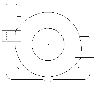
Below is a set of diagrams illustrating this issue. First, inwinger with relatively limited arm movement:

Then one with a lot more arm movement:

And finally the maximum amount the cheiroballistra design can hope to achieve:
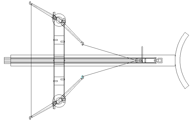
As can be seen, fully drawing back the bowstring is only possible if the arms rotate the absolute maximum amount, roughly 170 degrees. There's only one potential issue with this much rotation: the arm hits the curved field-frame bar at a ~60 degree angle when 90 degree angle would be safest for the bars.
Samuli.seppanen 17:05, June 19, 2011 (UTC)